
The Watness III [RE, Web]
Reverse engineer a WebGL game by reversing its fragment shader program. First RE and Web challenge from Plaid CTF 2021.
Challenge Description
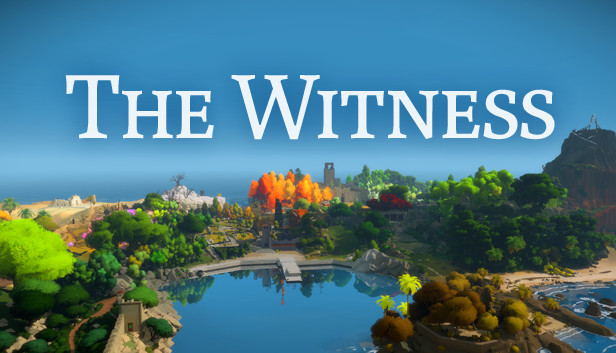
“Just when I thought I was out, they pulled me back in again.” From acclaimed writer Jimmy Glow comes the third entry in the Watness trilogy. Our hero is once again pulled into a world of puzzles and problems, with only their wit, persistence, and sheer force of will. Critics rave, “Why have you done this?”
Exploration
Disclaimer: This writeup will be quite long as I want to go a bit into the details of WebGL or even some working principles of OpenGL. Hopefully it will help you understand how I came up with my solution.
Also, I will be using “WebGL” and “OpenGL” quite interchangeably, since WebGL is just an API to apply OpenGL in the browser.
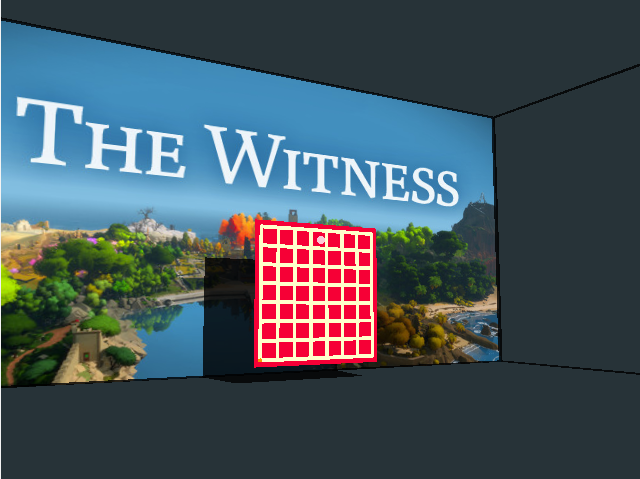
We are presented with a first-person game and we can draw line paths on a grid, that’s it. So the first thing to do is to open the developer’s console and look at the network and source tabs.

Finding the WebGL program
The only thing there is main.js. After beautifying and studying it, I realized that it’s a WebGL program, with no signs of game logic and/or winning condition. So I figured that I should see how WebGL even works before I can dig deeper.
Essentially, what OpenGL does is it takes each pixel value and passes through a couple of steps, called shaders. You can read on an overview of the rendering pipeline here.
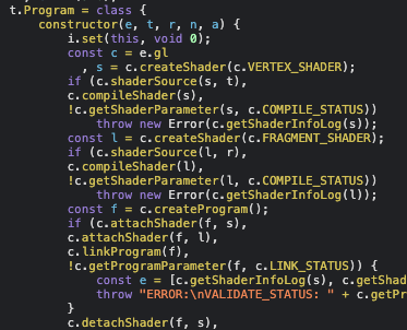
Here, I see VERTEX_SHADER and FRAGMENT_SHADER, since the JavaScript code doesn’t contain any winning condition check, I thought that it could only be in these two programs.
To find the source code, I first wanted to find where this WebGL program is created, so I looked at main.js more and found a main function that acts as the entry.
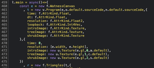
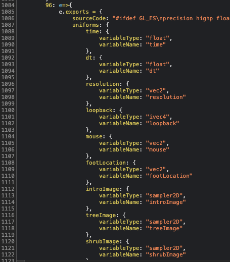
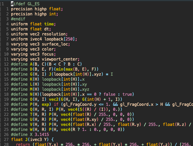
VERTEX_SHADER had nothing interesting. Image below shows the export of FRAGMENT_SHADER:
The source code looks like C, if we consult the OpenGL specifications we can see that it is a thing called OpenGL Shading Language, or GLSL, which is mostly similar to C. It has quite a number of built-in types and functions, you can read on it here or get a quick overview.
Understanding the logic
In this main function, I also found a loop:
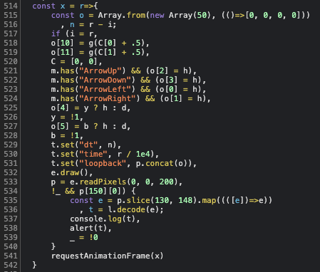
It seems complicated, but the important things are lines 533 and 534 in the if-statement. It takes the pixel values and checks whether the x-value of the 150th-indexed pixel is 0 or not (p[150] is a point represented by an array of four values which means RGBA or XYZW in GLSL).
Our goal should be getting p[150][0] != 0 and running the alert. So the flag should be the result of decoding the array related to pixels of index 130 to 147.
We can play around and see how the grid changes this pixel value. Breaking right after e.readPixels(0, 0, 200), and doing a console.log of the whole array:
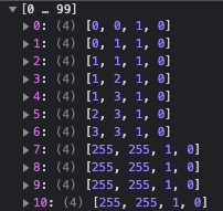
I realized that these corresponded to the line I drew (refer to the image above), in the format of [x, y, 1, 0]. Notice in every loop, p.concat(o) is set into the loopback field of the program, if we trace that line, we can see that this set action triggers a binder that updates the program.

This breakpoint is important, since it allows us to directly change loopback and test things out, remember this for references later on in the writeup. This updated loopback will be passed through the shaders to update the pixel values.
Reading the shader program
To make it easier to read, we can preprocess this code and replace the #define directives with the intended expression by running the C preprocessor:
cpp source.c clean_source.c
Then, throw it to a beautifier to get better indentations and line breaks. Some important things to note when reading this code:
- The input is given by
gl_FragCoord, which is the coordinate of the pixel that this shader is updating, and supplemented byloopbackand other fields. - The output is passed via
gl_FragColor, which should correspond to the color of the current pixel. - The shader starts in
main(), unsuprisingly…
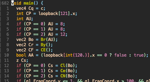
After inspecting Cl, Ce, CN, I found that CP is just the level that we are on. We can verify this by changing loopback[121][0] to 0, 1, 2 respectively: At the breakpoint mentioned earlier, do t[121][0] = ... to update.
Remember our objective? We need loopback[150][0] to not be 0. Looking in main we see this near the end:
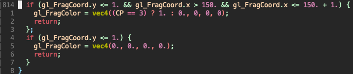
I found out that gl_FragCoord.x > 150. && gl_FragCoord.x <= 150. + 1. just makes sure that the current pixel is indexed 150.
Solution
So we have our objective here: Make CP == 3, but it isn’t as easy as changing the value at that breakpoint, since the final flag is dependent on pixels index 130 to 147.
void main() {
  ...
  if (Cs.AB && AD(viewport_center, Cv.v) < 2.) {
    CP = CP + 1;
  }
  ...
}
This block suggests that we advance a level every time Cs.AB == true (not sure what the other term does, so I ignored it). At level 2, we will have CP = 2 + 1 = 3 if we solve it!!!
struct z {
  bool AA;
  bool AB;
}; // This essentially is a boolean pair
...
void main() {
  ...
  // We need these to return {XX, true}
  z Cs;
  if (CP == 0) Cs = Cl(Bo);
  if (CP == 1) Cs = Ce(Bo);
  if (CP == 2) Cs = CN(Bo);
  ...
}
Level 0
z Cl(vec2 Bo) {
  ...
  bool Bp = Bj(8);
  ...
  return z(AA, Bp);
}
The value that we want to control is affected by Bj(8) only.
// Bj(8) => AU = 8
bool Bj(int AU) {
  for (int AO = 0; AO < 100 - 1; AO++) {
    ivec3 Aj = loopback[int(int(0.) + AO)].xyz;     // Current point
    ivec3 Ag = loopback[int(int(0.) + AO + 1)].xyz; // Next point
    if (Aj == ivec3(255, 255, 1)) {
      return false;
    }
    if (Aj == ivec3(AU - 1, AU - 1, 1)) {
      // We want to reach here to return true
      // Aj == [7, 7, 1] which means we should pass through (7,7) in the grid
      return true;
    }
    // Mean of x values of current and next pixel, then dividing by AU = 8
    float Bk = (float(Aj.x) + float(Ag.x)) / (2. * float(AU));
    // Mean of y values of current and next pixel, then dividing by AU = 8
    float Bl = (float(Aj.y) + float(Ag.y)) / (2. * float(AU));
    vec4 Bm = texture2D(introImage, vec2(Bk, Bl));
    if (Bm.a >= 1.) {
      return false;
    }
  }
  return false;
}
I’ve added comments to indicate what each line represents. The thing to take care of is to avoid the case of Bm.a >= 1. at all costs, at least before we reach (7, 7).
But what does texture2D(introImage, ...) do? According to the description of the function, it takes the pixel of introImage at the specified coordinates and returns it.
But from the comments I’ve put, the x and y values are divided by 8, this is because OpenGL wants to normalize the coordinates such that the image dimension doesn’t affect the coordinates that needs to be passed in (read about it here).
And due to normalization, Bm.a >= 1 means that the alpha value of that pixel is >= 255, which essentially means == 255 since it cannot exceed 255.
Looking around the JS code, we find the image that is represented by introImage. I downloaded it and wrote some python code to process it:
from PIL import Image

img = Image.open('introImage.png')
result = Image.open('introImage.png')
for x in range(img.width):
  for y in range(img.height):
    # Pixels are in RGBA format
    # Since PIL has (0, 0) at the top-left corner but our grid starts at bottom-left
    # we have to invert the y-value of the pixel for the output
    if img.getpixel((x, y))[3] != 255:
      result.putpixel((x, y.height-y-1), (0,0,0,255))
    else:
      result.putpixel((x, y.height-y-1), (255,255,255,255))

result.save('path.png')

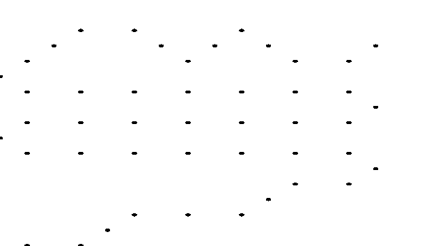
The black dots represent the “mid-point” that we can pass through, which means our path should look something like:
And…?
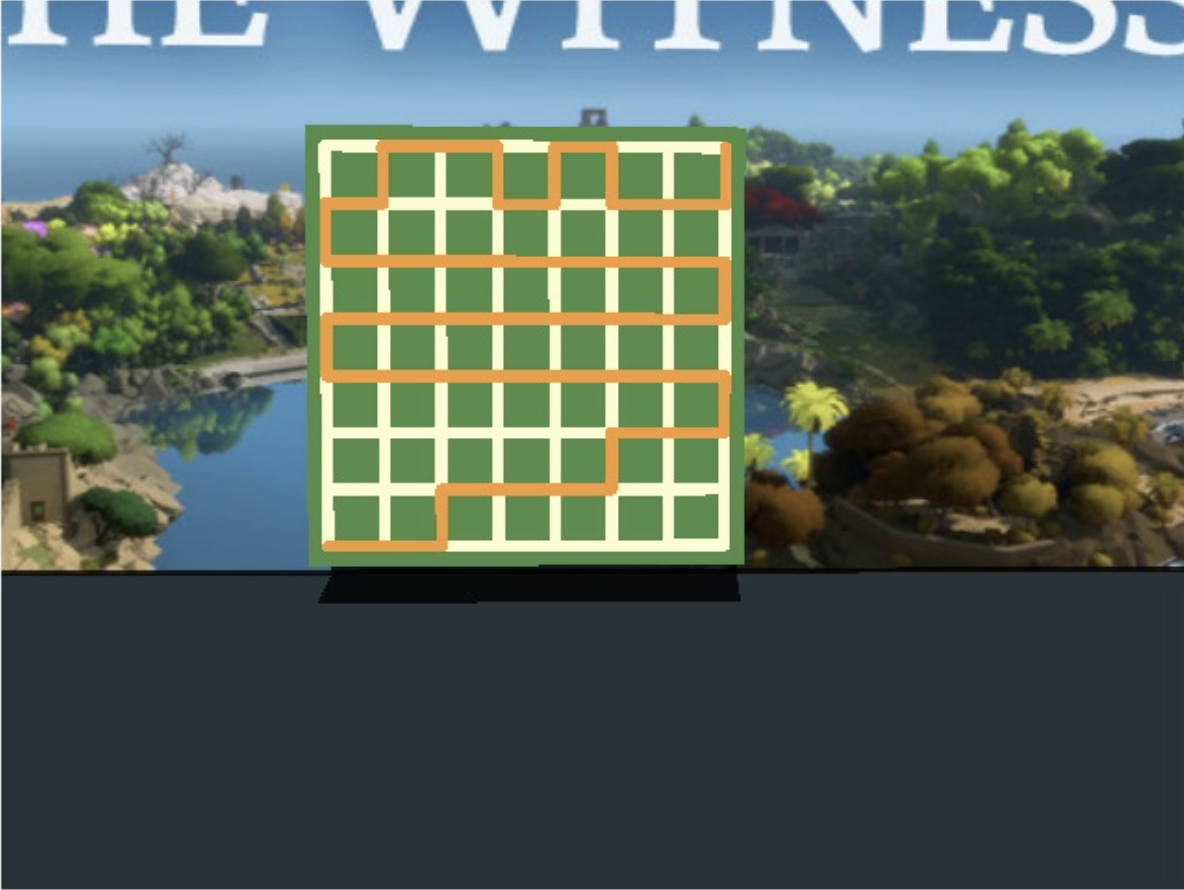
It works! Next level~
Level 1
Jumping straight to the function for this level:
z Ce(vec2 Bo) {
  ...
  bool Bp = Bi(8);
  ...
  return z(AA, Bp);
}
So it’s basically the same thing as last level. We need Bi(8) to return true.
bool Bi(int AU) {
  for (int AO = 0; AO < 100 - 1; AO++) {
    ivec3 Aj = loopback[int(int(0.) + AO)].xyz; // Current point
    if (Aj == ivec3(255, 255, 1)) {
      return false;
    }
    if (Aj == ivec3(AU - 1, AU - 1, 1)) {
      // Again, we need to reach (7, 7) in the grid
      return true;
    }
    // AP(y*8 + x, 2) where y*8 + x is sort of indexing the grid points
    /*
      56 57 58 59 ... 63
       .  .  .  . ...  .
       8  9 10 11 ... 15
       0  1  2  3 ...  7
    */
    int R = AP(float(Aj.y * AU + Aj.x), 2.);
    // We want the result to be 1 at all times before we return
    if (R != 1) {
      return false;
    }
  }
  return true;
}
Here’s AP, and AK which is called in AP:
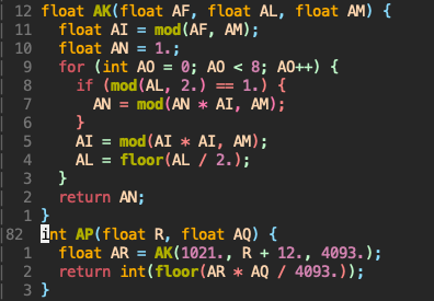
Notice that AK is just binary exponentiation, essentially AK(a,b,m) == pow(a,b,m) in python. So we can write some code to find which points can be travelled to.
# Inverting i because (0, 0) is bottom-left
for i in range(7, -1, -1):
  for j in range(8):
    AR = pow(1021, 8*i + j + 12, 4093)
    AP = AR*2//4093
    if AP == 1:
      print('O', end='') # Can travel
    else:
      print('#', end='') # Can't travel
  print()
Output:
OO##OOOO
O####O##
##OOOOO#
O#####OO
OOO#OOO#
O#OOO###
O##O##O#
OO#OOO#O
Level 2
z CN(vec2 Bo) {
  ...
  bool Bp = BZ(12);
  ...
  return z(AA, Bp);
}
Again, same thing:
bool BZ(int AU) {
  ivec2 Ba[14];
  Ba[0] = ivec2(2, 6);
  Ba[1] = ivec2(2, 4);
  ...
  Ba[12] = ivec2(10, 4);
  Ba[13] = ivec2(11, 7);
  ivec2 Bb[14];
  Bb[0] = ivec2(0, 7);
  Bb[1] = ivec2(2, 7);
  ...
  Bb[12] = ivec2(10, 10);
  Bb[13] = ivec2(10, 7);
  int Bc = 0;
  int Bd = 0;
  for (int AO = 1; AO < 100 - 1; AO++) {
    ivec3 Be = loopback[int(int(0.) + AO - 1)].xyz; // Previous point
    ivec3 Aj = loopback[int(int(0.) + AO)].xyz;     // Current point
    ivec3 Ag = loopback[int(int(0.) + AO + 1)].xyz; // Next point
    if (Ag == ivec3(255, 255, 1)) {
      return false;
    }
    if (Ag == ivec3(AU - 1, AU - 1, 1) && Bc == 14 && Bd == 14) {
      // Reach (7, 7) and two other conditions
      return true;
    }
    vec3 Bf = vec3(Ag - Aj); // Direction from current point to next point
    vec3 Bg = vec3(Be - Aj); // Direction from current point to previous point
    // Let:
    // Bf = (x1, y1)
    // Bg = (x2, y2)
    vec3 Bh = cross(Bf, Bg); // Cross product
    if (Bh.z != 0.) {
      // Notice that the z-term's coefficient of a cross product = x1y2 - x2y1
      for (int BV = 0; BV < 14; BV++) {
        if (Bh.z < -0.5) {
          if (Bd >= 14) return false;
          if (BV == Bd) {
            if (Bb[BV] != Aj.xy) return false;
            Bd++;
            break;
          }
        }
        if (Bh.z > 0.5) {
          if (Bc >= 14) return false;
          if (BV == Bc) {
            if (Ba[BV] != Aj.xy) return false;
            Bc++;
            break;
          }
        }
      }
    }
  }
  return false;
}
This is a lot to digest, we have two more conditions to satisfy: Bc == 14 and Bd == 14. Along with this, we have a for loop to update these two variables. Take some time to read it, and you will notice that the vector array Ba and Bb are related to Bc and Bd respectively. Looking at the z-term of the cross product, we can try out different combinations of “direction”, and find that Bh.z < - 0.5 when the path does a “left turn”, with the other case being a “right turn”.
The for loop and other if statements basically make sure that each array of vectors have the points they represent travelled in their respective order. In simple terms, Ba[2] cannot be travelled before Ba[1] and Ba[0] etc. Each correct traversal will increment Bc and Bd, so that means we need to traverse all points in the correct order and “turns”.
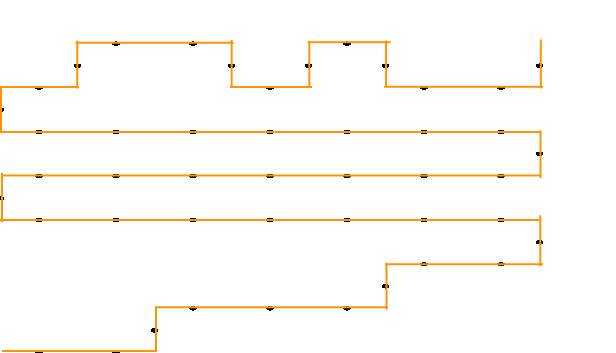
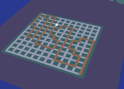
To solve this, I drew out the 11x11 grid and labelled the points that have a specific turn, this is the result:
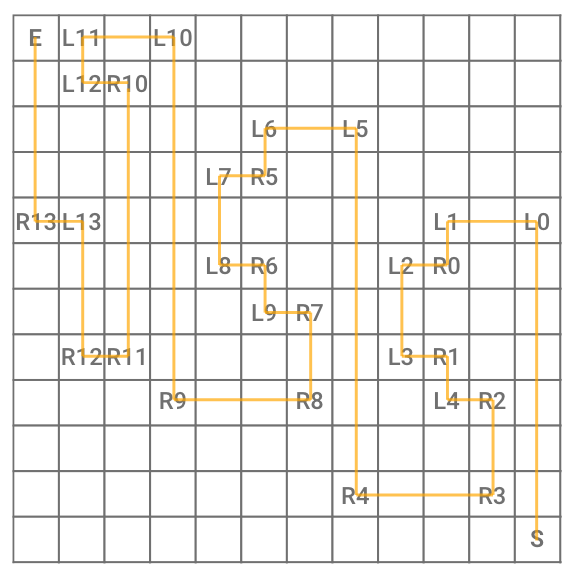
Notice that we start at the bottom-right in this stage. However, I was unable to draw on the grid (maybe I missed out on something), so I resorted to using the breakpoint from earlier to write the values to the first few indices of loopback.
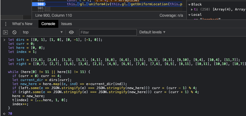
Here’s the code:
let dirs = [[0, 1], [1, 0], [0, -1], [-1, 0]];
let curr = 0;
let here = [0, 0];
let index = 1;

let left = [[2,6], [2,4], [1,3], [1,1], [4,1], [6,8], [6,6], [5,5], [5,3], [8,3], [9,10], [9,4], [10,4], [11,7]];
let right = [[0,7], [2,7], [3,6], [3,4], [2,3], [4,9], [6,9], [7,8], [7,6], [6,5], [8,11], [10,11], [10,10], [10,7]];

while (here[0] != 11 || here[1] != 11) {
  if (curr < 0) curr += 4;
  let current_dir = dirs[curr];
  let new_here = here.map((e, ind) => e+current_dir[ind]);
  if (left.some(e => JSON.stringify(e) === JSON.stringify(new_here))) curr = (curr - 1) % 4;
  if (right.some(e => JSON.stringify(e) === JSON.stringify(new_here))) curr = (curr + 1) % 4;
  here = new_here;
  t[index] = [...here, 1, 0];
  index++;
}
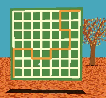
Disable the breakpoint and continuing the execution:
Final Script
Level 0
from PIL import Image

img = Image.open('introImage.png')
result = Image.open('introImage.png')
for x in range(img.width):
  for y in range(img.height):
    if img.getpixel((x, y))[3] != 255:
      result.putpixel((x, img.height-y-1), (0,0,0,255))
    else:
      result.putpixel((x, img.height-y-1), (255,255,255,255))

result.save('path.png')
Level 1
for i in range(7, -1, -1):
  for j in range(8):
    AR = pow(1021, 8*i + j + 12, 4093)
    AP = AR*2//4093
    if AP == 1:
      print('O', end='')
    else:
      print('#', end='')
    print()
Level 2
let dirs = [[0, 1], [1, 0], [0, -1], [-1, 0]];
let curr = 0;
let here = [0, 0];
let index = 1;

let left = [[2,6], [2,4], [1,3], [1,1], [4,1], [6,8], [6,6], [5,5], [5,3], [8,3], [9,10], [9,4], [10,4], [11,7]];
let right = [[0,7], [2,7], [3,6], [3,4], [2,3], [4,9], [6,9], [7,8], [7,6], [6,5], [8,11], [10,11], [10,10], [10,7]];

while (here[0] != 11 || here[1] != 11) {
  if (curr < 0) curr += 4;
  let current_dir = dirs[curr];
  let new_here = here.map((e, ind) => e+current_dir[ind]);
  if (left.some(e => JSON.stringify(e) === JSON.stringify(new_here))) curr = (curr - 1) % 4;
  if (right.some(e => JSON.stringify(e) === JSON.stringify(new_here))) curr = (curr + 1) % 4;
  here = new_here;
  t[index] = [...here, 1, 0];
  index++;
}
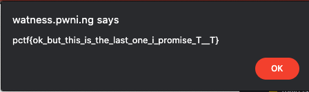
Flag: pctf{ok_but_this_is_the_last_one_i_promise_T__T}